

I will admit, I am not an Aerodynamics expert.
But, in 2023, there is a lot of data to use about all sorts of Aerodynamics, and this isn’t hard.
So, to Begin;
Aerodynamics is how Air reacts and flows around or through an object.
Drag is the air resistance over an object. This includes multiple different vectors and factors, including pressure, vacuum, and friction.
Drag Coefficient is a number used to determine the real drag of an object, or how a fluid reacts to it.
Streamlining is the design principle in Aerodynamics of reducing Drag by altering the form of an object, removing surfaces horizontal to the flow and removing areas of low pressure or where air may be trapped and thus create drag.
Buff is the opposite of streamlining.
The different forces of Drag can be used in a range of different ways, and we understand this fairly well at this point. The Wingless Wonders such as Nasa’s X24 are an example, using a combination of different drag features to generate lift.
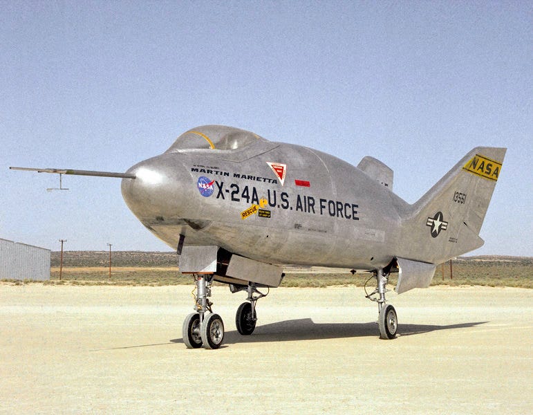
the underside of the aircraft is designed to generate Lift with high pressure underneath, while the back is designed to make lift by generating low pressure above and behind it, pulling it up.
However, we are not talking about Aeroplanes, but Trains. Specifically, Steam Locomotives designed in the United Kingdom.
In My Opinion, There are some inconsistencies in how we view different locomotives, values and features. So, to begin, we are going to look at the Definitive streamlined express locomotive.
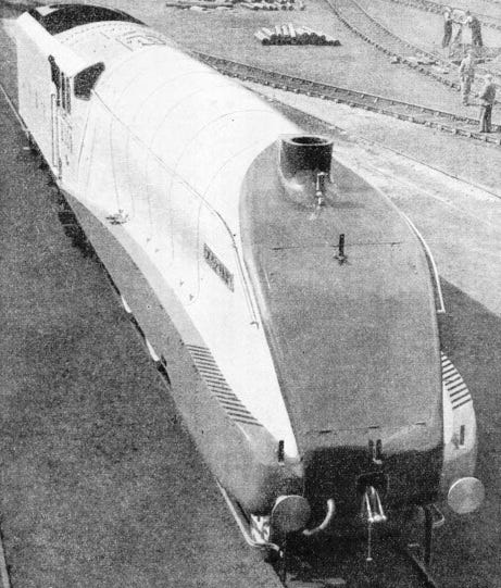
LNER A4
The LNER A4 was designed by the CME’s Department in Doncaster, England. for the expressed purpose of being a streamlined express locomotive to pioneer ahead with the new Jubilee and Coronation expresses. Starting service in September 1935, Silver link not only set records for Speed, but ran the Express, both ways, every day for 10, non-consecutive days, without a failure, running successfully with an average timing being ahead of schedule by minutes. A lauded success in both effectiveness and efficiency, Silver Link was a masterpiece in motion, and was complimented by the coach sets also designed for speed, which featured many of the newest technologies and materials.
Aerodynamically speaking, the A4’s air flow primarily is intended to push up, over the engine and sit like a cushion of air over the top of the locomotive, which pushes smoke up over the locomotive, and allows the driver a clear view forward. the wide front nose and flat top at first seeming illogical, but encouraging this effect.
To the left and right, the boiler cladding feeds back smoothly to the sculpted cab front designed to push the air to either side.
Then down, the Valences cover over the wheels and reduce drag induced in the operation. The locomotive is completely encased in it’s streamlined bodywork.
LMS Princess.
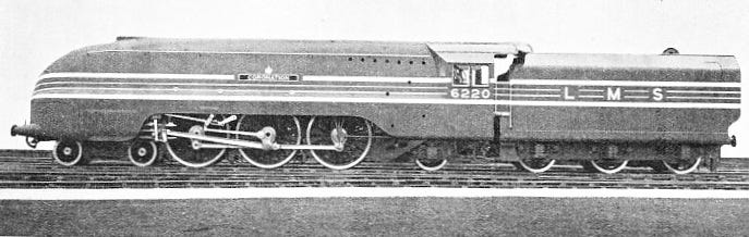
The less than fortunate rival to the LNER’s A4s, the Princesses and Coronation streamliners had less development time than their counterpart. Where the LNER’s A4 was built on the the long-standing A1/A3 chassis and boiler, The Princesses had only be four months old when Silver Link would surface, and would not be streamlined until June 1937, nearly two years later.
The design is best described in aerodynamic terms as a Secant Ogive. Put simply, it’s half-round. It’s one of the oldest forms of Aerodynamic profiles and is generally the simplest, the rounded top would mean that there was no generated cushion of air, but rather there would be down-draught at speed that pulls smoke down, giving the class poor visibility when Streamlined.
But it is mostly streamlined, covering over most points of resistance, excluding the wheels and operation.
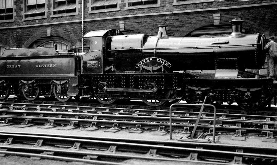
GWR King and Castle.
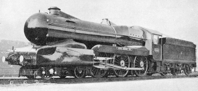
King Edward VIII was already a service locomotive before receiving the modifications in the spring of 1935, nearly three months before the A4 and at the same time as the Princess initially rolled out as a locomotive.
Unlike the other two, the King was not wind-tunnel tested, but for the most part, the streamlining applied was common-sense. With an Ogive nose over the front of the boiler, then using the aerodynamic properties of the long boiler, the design reduces low-pressure Drag by filling the areas behind the Chimney, reducing the smoke being pulled down, maintaining visibility. the conical linking from the Belpare firebox to the boiler and V-form cab reduce the air-resistance by presenting less flat area to block the wind and form pressure resistance, and the gap between the locomotive cab and Tender is filled, reducing low-pressure or vacuum drag. Meanwhile, the normally very square front end and flat cylinder faces are covered in a shaped sheet which curves around them, so that the amount of front-facing vertical faces is limited to just the Buffers and Bufferbeam.
This design gets a lot of flak on the grounds that it was not Scientific, and was not put through a wind-tunnel, but in reality, it features aerodynamic features with a level of sensibility, identifying and altering areas where drag is a problem. It presents a more affordable and realistic alternative for streamlining than the Coronation and A4. But it is undermined in it’s ultimate practicality.
Unlike the LMS and LNER, the GWR did not have any major long, fast straight lines to push for high speeds. The King was already a heavy locomotive and restricted in it’s operation, and though a Castle was also streamlined, in the end, the streamlining was reducing air-cooling on major parts, leading to overheating, and high maintenance in regular service. It was Uneconomical to have a streamlined service when the engines were not really even reaching their top speeds regardless, and all the streamlining did was cause increased maintenance.
In 1955, Kings were achieving 108 miles per hour, unstreamlined when track conditions gave them the ability to do so, and after improvements to draught, while Castles, generally smaller and in lower power classes to A3s and A4s, were recorded performing at 100mph with minor tweaks post-war.
The simple fact is that Kings and Castles were not horrendously Buff. That is, unstreamlined. The large, tapered boilers and rounded shoulders of the Belpare fireboxes gave them very good visibility and air flow, and on regular service trains they were regularly performing in the low 90 mph comfortably in the 1930’s, with services regularly holding average speeds of 70mph plus on the level. The greater argument, perhaps, is that they were never given the same opportunities for speed as their counterparts, so never Needed it.
So the Heart wasn’t there. But, in terms of Aerodynamics, was the engine particularly bad?
Well… No. Taking a frontal view, there isn’t any immediate form of Drag that stands out, beyond the safety valve crown on the boiler, and perhaps the gap between the back of the cylinder exhaust and the splasher. It is criticised that it is Not an all-encompassing body like on the other two, but what does that really mean?
It means it costs more, takes longer to fit and repair, lowering availability and reliability, for marginal benefits on the road.
Southern Light Pacifics
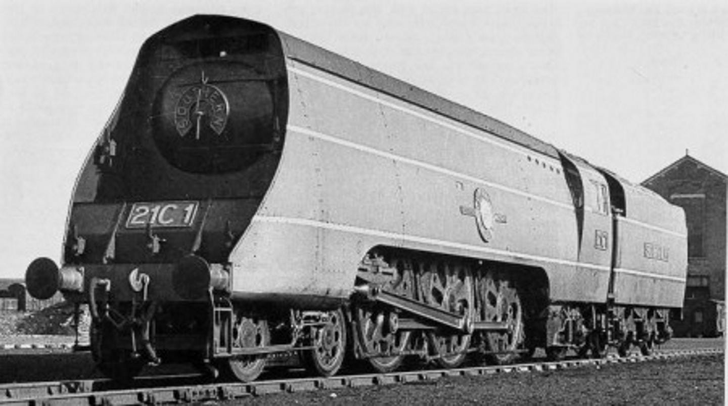
the Southern Light Pacifics Should Not be on this list, They are never called Streamlined, but instead are referred to as Air-Smoothed. But they are to illustrate a key concept. In effect, they are an honourable mention.
Wind-tunnel testing does not mean that a design is Aerodynamic or Streamlined. And a design may not be Streamlined.
Key to the continuation of this is a few features seen here on 21C1 Channel Packet. The sweeping front profile of the cladding, the stepped front and, above the smokebox, an air-channel directing the air trapped at the front of the locomotive back and over the top of the locomotive. In effect doing the same as the A4’s sweeping front.
The front of this locomotive is Buff, that is, it is flat and inherently generates a zone of high pressure caught infront of the locomotive with no means of escape. This is the Opposite of Streamlining, but can be used to good effect to encourage high-pressure draughting, if that is what may be required. The sides offer little or no Drag, and the flat top, like the A4, allows for a pressure cushion which reduces smoke obscuring the driver.
This design was produced by OVS Bullied, and design starts from 1938. But Bullied had worked in the CME’s Department at the LNER, and had experience on the A4 and it’s predecessors, Indeed, some could argue that it takes lessons from them.
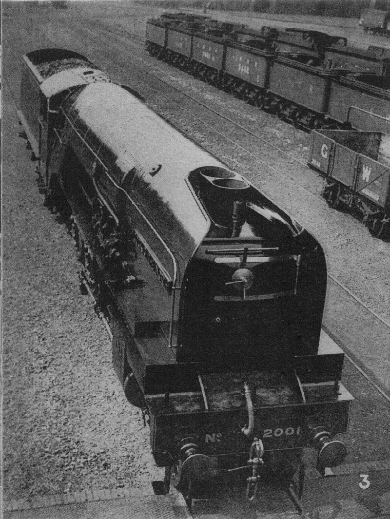
LNER W1
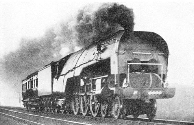
The W1 is more complex than the other locomotives in normal consideration. Built by mating the A3 Chassis to a Yarrow water-tube boiler, it is made in to a 4-6-4 as it has to be extended to accommodate the new boiler, which is very tall, and combined, the two Just fit inside the British loading-gauge (the space that locomotives and rolling stock have to fit within to not foul bridges and platforms.)
To understand the design of the W1, you have to understand the compromises between the boilers, and why W1 was never going to succeed.
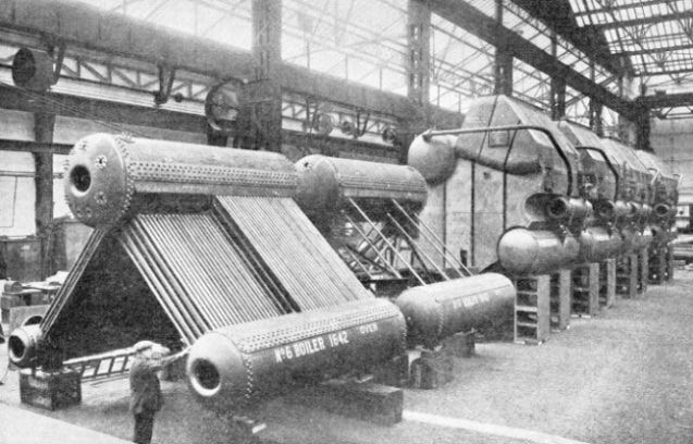
A normal boiler is a tube filled with water, through which run tubes which carry a source of heat, that transfers the heat to the water. In a steam locomotive, this is a fire, in the Fire-box. At the other end, there is the Smoke-box, with the chimney out the top. A combination of air-flow out from the Blast-pipe (Exhaust from the cylinders) and low air-pressure in the chimney sucks the hot air through, and in the process provides the draught, sucking the air in to the Fire.
W1’s Yarrow water-tube boiler instead had a rib-like series of tubes filled with water that would be heated directly over a larger fire, which is more efficient in heat transfer, but needs more Air, and it does not draw air through in the normal means.
This is made worse by a short Chimney, and Compounding.
the short Chimney means there is less draw from that, and Compounding means there is less pressure being pushed through the blast-pipe, but both are essential; the boiler is already at the top of the gauge, so that is not possible, and the compounding is necessary to fully and efficiently utilise the higher pressures found with the Yarrow boiler. This also means there is less draw, less air, going in to the fire which needs more because it’s bigger.
W1 is a Catch-22; to use the more efficient water heating unit, you lose all of the normal methods of making the heat in the first place. Normally, these boilers are used in Ships and power-stations, and would receive drafting from Fans, or tall chimneys.
With that in mind, the front of the engine has two jobs.
The Lower Half of the front is vertical, and has three gaps in it; one to either side, and one in the centre. These force air in to “Internal Streamlining” which routes air around the boiler, acting as an insulating jacket between the cladding and the boiler, then takes that hot air round and down to the back of the firebox and pushes it forward, reproducing the normal vacuum draught of the normal firebox. This is assisted by a fan at different points. But, fundamentally, the lower half of the locomotive’s frontage is Buff.
The Upper half of the front end of the locomotive is angled between 20 and 30 degrees, and curves up to vertical behind the chimney. The smoke shields curve in to compress air in to this area, to push smoke up and form that air cushion mentioned on the A4 and Merchant Navy. And like the Merchant Navy, this is Compression, which slows down air and forces back against the locomotive, it’s Buff.
But the herringbone curved spine of the W1, demanded by the herringbone Yarrow boiler, spoils the intent anyway.
The combination of quickly sloping sides, with the ribbing of the aluminium banding, results in a general trend to suck air down. This is observed to a degree on regular locomotives, but the curve of the boiler means the forces involved are generally balanced and equal. First it sucks down the pressure buffer set by the smoke shields, then it sucks down the smoke, giving it the same result as the Coronation. To combat this, the engine has the flat strip along the top.
This is often cited as the External Streamlining, as this presents a smooth top surface and the absence of the Dome does not break the air pressure cushion before creating low pressure which pulls smoke down. But this is not an additional, intentional feature by Gresley; the Yarrow boiler doesn’t have a Dome in the first place, to be Removed. The top cylinder handles that. It’s also not a new feature in Railway Engineering, either.
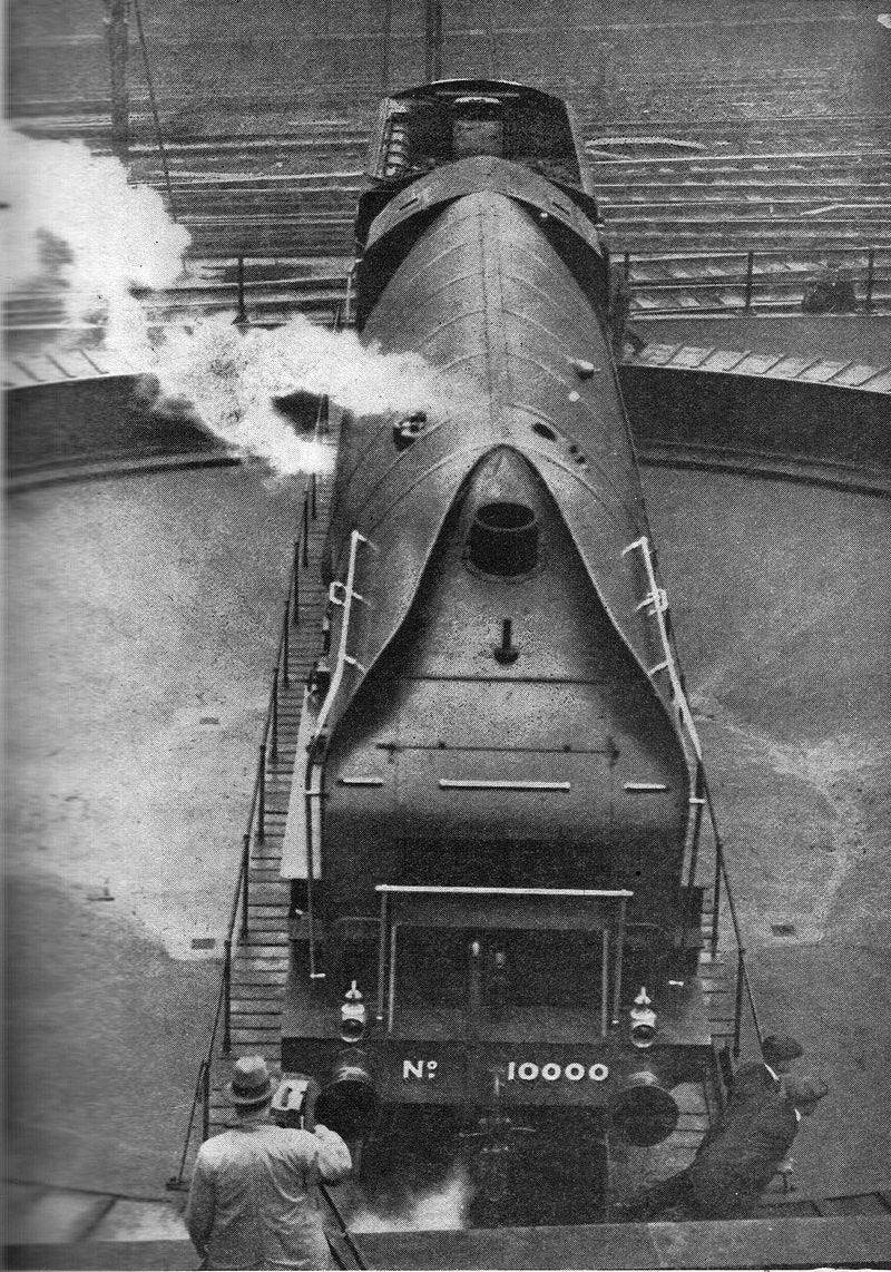
If the King should be discredited because it is not Scientific, then the W1 should perhaps be considered so because it is Inevitable. The only actual streamlining feature, that is it reduces drag against a normal locomotive, is the flat boiler top. All the features of W1 are effectively dictated by the Yarrow boiler; the flat top, the herringbone sides, the internal drafting. Other than that, the locomotive’s front is Buff. As is it’s Cab. And, if you refer back to the first and second images of it, a second, and perhaps more egregious example of Buff design can be seen.
Considering the GWR King, The locomotive featured for it’s testing, A linking roof to reduce the impact of pressure differential drag coming off the back of the cab.
The W1’s Cab matches the profile of the Boiler, cutting higher than the Tender behind it, but also cutting narrower than it. This means there are two, square, Buff wings poking out behind the cab. Wings which, themselves, have a second set of air-smoothing smoke-deflector shields that, behind an A3, would mean that there is less air cutting in to the Cab’s low pressure.
What this actually does for W1 is catch wind off the cab, and directs it down and in like a scoop, adding yet more Drag. And there’s no real reason why the W1 has this as a flaw.
The W1’s front profile and general form does spend a lot of time in a rudimentary wind tunnel, but all of that is going to Just getting the Yarrow Tube Boiler to work. What little Streamlining is there, the roof-spine, is doing very little and is simply there to capitalise on the one thing W1 has going for it.
Is the W1 Streamlined? It’s certainly Wind-tunnel-tested, It’s certainly Aerodynamic, but all of that is just to try and get it to Work. And in the end, there are just too many Buff features that stand in opposition because of it’s core construction, trying to work around the Yarrow boiler. In terms of being Streamlined, it is debatably worse than the GWR’s example.
That is not to undermine the efforts by Nigel Gresley; even the Buff features are structured and designed toward the end goal of making the Yarrow boiler work on a British Steam Locomotive. Which was the intent, and it was successful within it’s remit.
P2; /1Cock O’ the North. P2/2 and P2/3.
The differences between P2/1 P2/2 and P2/3 are simple; P2/1 was designed experimentally, with alterable parts and experimental running gear, while the others were meant to be a more standard class, P2/2 changing the gear to tried-and-tested formats, and then P2/3 was an external alteration, in Streamlining.
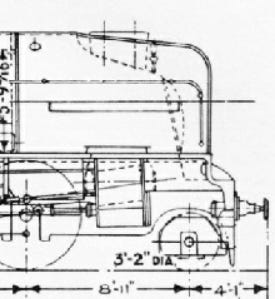
Unlike the previous W1, to which the front buff designs can be attributed to the Yarrow boiler, P2/1 used the same front profile because it seemed to work on W1. Only this time, the lower buff was raked back by 10 degrees, and the more angled V behind the chimney on the W1 is replaced with a rounded, U shape to accommodate the rounded double chimney.
The question, really, is Why? Many of these decisions are born from necessity on the W1, but the P2 has a regular boiler. It doesn’t have to be at the top of the loading gauge, and it doesn’t have to use this peculiar method of raising smoke.
And, for the eagle-eyed, there are some issues.
The obvious Intended route for air-flow would be;
trailing up, over the front of the firebox front, then up the curve behind the chimney.
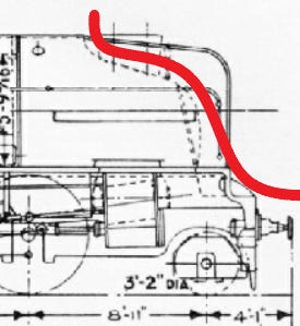
But a cursory look shows this;
Though Some air will go up the intended path, there is a problem with Buff feeding in to compression.
The air hitting the front of the locomotive smokebox, though much of it will go to the side and then up, there is an air trap, and where the W1 had air from the Buff going in to the locomotive, on the P2, it’s going straight up, Compressing, and then forming a pressure curtain riding just within the wings, which is making it’s own aerodynamic bubble, forcing new air up and over, overriding the pressure going across the back of the chimney in pushing smoke down. The dynamic balance that worked on the W1 was not working on the P2 because the air utilization was different.
Besides;
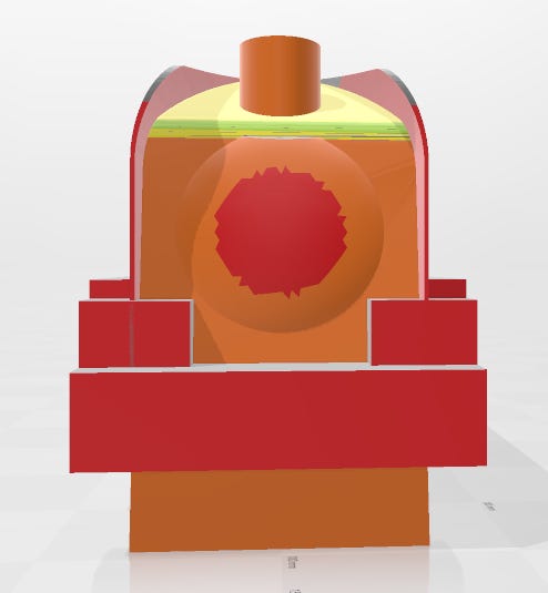
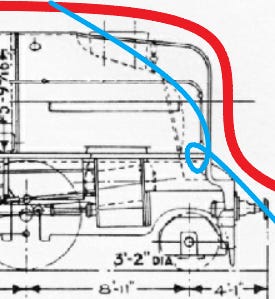
The areas marked in red are Buff; Flat, unstreamlined and pointing towards the oncoming wind. The orange is somewhat sloped, then improving in colour, the yellow and green are the sloped air control. The Cad work is very crude and inaccurate, but it makes it’s point; the P2’s front end was Buff. Not streamlined.
P2/2, Earl Marischal is the same, but recognising that there was still a problem with smoke, the first answer was to add smoke deflectors with internal fins, pushing air up the side of the original wings, creating a second draught which comes in behind the originally intended one. In the process, the running board is lowered, and the new fins covered a lot of the square, buff, clutter. Though I can’t be sure, it would appear that the front smoke box was pressed more to level, which I can only presume was to open the smokebox door easier.
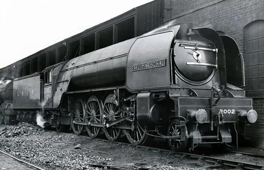
For some reason, the handrails are all wrong in this image; on the right hand side, they run pointlessly behind the plate, while on the other side, they run on the outside, just reinforcing the point that there was something wrong. P2/2 had the gear changed, and in the process, an odd bit of streamlining, a cowling covering the top half of the cylinder, was removed. Presumably having observed a similar heating issue to the GWR.
P2/3 is the final, and most numerous version of this design, and it finally solves the class’s streamlining problem by just giving the engines the nose from the A4. The P2/1 and P2/2 are refitted to P2/3, because that design actually solves the Smoke problem for the class, but they’re still notorious as a class. The W1 also gets a boiler and streamlining refit, turning the P2s in to Long A4s, and W1 in to Spare-wheel A4.
Again, despite being Wind Tunnel Tested, The P2s are very Buff and they suffer because of obvious wind-traps designed to do one job, but then not tested at higher speeds and pressures when they change and do another. Aerodynamically speaking, if the engine is travelling too slowly, then the updraft is not being created, and if they are going too fast, then it is simply creating a buffer, directing the air away to push smoke down. The only Streamlined feature, again, is the covered dome, taking lessons from W1. Unlike W1, however, the P2 has the same cab profile as the A3, and so does not have the air-trap tender, and the P2 has a V form cab, which offers some streamlining, but marginal benefits.
So is the P2 streamlined? P2/3 is, but P2/1 and P2/2 suffered chronically from “Golden Zone” testing, where testing a design in an ideal air speed gets perfect results, but outside of that small window, air behaves differently and then they don’t work properly. And where W1 Benefits, with more air going in to the fire, P2 gains nothing from having this. And the answer to fix P2/2 illustrates a fundamental inability to fully understand what went Wrong, so the answer is rather to add more, rather than fully redesign.
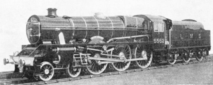
LMS 5XP, or the “Jubilee” Class.
The Jubilee was built in 1934 to replace the outdated Stephenson and Experiment class of LNWR 4-6-0s that were now life-expired but still running the crack expresses.
And, at first, you might think, “That isn’t Streamlined”
But consider, for a moment.
The immediate front presents little, but in working back, it’s the little things. The Chimney form is subtly designed to reduce Drag, the dome is made as short as it can be, the boiler banding is flush and the other fittings minimalised and slimmed, the cab front has a slight V-form, the Tapered boiler reduces the profile of the Firebox and the Belpare is canted so as to push air Up, over the safety valves and cab roof with a minor area of low-pressure, countered by the flat cab end to become an area of Nul-pressure, or a Buffer zone, at speed. The glass windows reduce drag by limiting the opportunity for air to go in to the cab and the Tender profile is designed to match the Cab, so that as the Cab cuts through the air, the Tender follows, and their profiles match the standard Coach profile, to reduce intermediate drag by setting one, smooth profile, reducing drag in to the gaps between coaches.
And, Like the Gresley engines, It was tested in a Wind-tunnel. But unlike the A4, King and Coronation, the technical beauty of the 5XP is not in Building a case around the locomotive to improve it’s streamlining, but to Design the locomotive to make best use of Aerodynamic properties, which wastes less material, improves the engine designs going forward and solves or avoids common mechanical issues found by other designs. A more technical and scientific method of using wind-tunnels.
GWR Bulldog class.
The Bulldog class, and it’s successors, display many admirable traits in the exploration and assertion of Streamlining; Featuring Dual frames, the outside frame acts as a valance, reducing air contact with the spokes and the resultant drag and vortices, the Tapered boiler flush in alignment with the Belpare at the top and sides minimises the relative displacement and Buff of the Belpare, while still capitalising in it’s benefits. The slimline brass ornament in the centre of the boiler takes the place of safety valves, top feed and Dome in to one sleek unit. The reduced height tender provides an area for Pressure Equalization coming off the back of the Cab, which is unfortunately not V-form or streamlined, but Core principles of Aerodynamics are displayed in these locomotives, with the Birds, a sub-section, having reduced rivets and bolts on the side. Internally, the blast-pipe and cylinders are arranged to allow for a smooth ideal draft to pull air through the fire, and the GWR’s Jumper Top Blastpipe allowed for adjustment and alteration to calibrate and optimise the air-flow, or internal streamlining.
What does this mean?
In the dark dawn of early Railways, two men of science stood apart.
Doctor Dionysius Lardner, and Isambard Kingdom Brunel.
Lardner argued that Brunel’s Box Tunnel was dangerous because trains would rapidly accelerate, like a bullet in a gunbarrel.
Brunel pointed that Lardner’s math was illogical, and did not factor in Air Resistance and Drag.
And later, when one of Daniel Gooch’s engines were performing poorly, Lardner argued that this was because of Air Resistance and Drag, reciprocating Brunel’s comment. Brunel and Gooch carried out their own experiments on the locomotive and found that the only problem was that the blast pipe was too small.
Aerodynamics and Streamlining, both inside and outside of the locomotive, were around long before the Mallard; Lardner and Brunel was 1838, almost a Century before. They are core vectors which have been pervasive in all locomotive design.
Is it conceivable that Gresley knew about Aerodynamics and Streamlining and factored it in to the W1 and P2? Inevitably. So did whomever did the GWR King, or the Dukedog. It’s been there since the Iron Duke. Aerodynamics were not an invention of the 1920’s, but a core engineering principle that factors in to everything.
The question is not what it is, and if it was known, but how it was applied, and it’s effectiveness.
So, Was the P2/1 Streamlined? In some ways. Yes. In other ways, No. Overall, I would say No.
And the same applies for the King; But the King’s Streamlining, regardless of how it came to be, was Better, it was just not given the same regard.
But at the same time, there are plenty of other developments that may also increase or inhibit a locomotive’s performance. Just as Brunel’s Iron Duke did not need streamlining, the King did not need it a century later; some tweaks to drafting elsewhere, some better track and facilities, and the King could achieve the same as the streamlined A4 could.
The Jubilee is, perhaps, the only actually Streamlined Locomotive there, as the others rely on external cladding over an already existing engine, where the Jubilee is integrally designed with aerodynamic properties in action.
So the real question is; Why do we stand by some designs more than others? Defend them to the Hilt? How is W1 a Streamliner while the legitimacy of Tregarren Castle in doubt?
It is because we are not Critical, and we decided that W1 Looks pretty, and Looks like it’s Streamlined. While the Castle looks like a Steam engine with bits. Steampunk. And the Jubilee isn’t clad at all.
How Hypocritical. How Opinionated. And, of course, it’s Justified because it’s based in Facts. Such as that Collett did not care, unlike Gresley, who practically Invented the Wind-tunnel to test his W1.
Just because there’s more working out, doesn’t mean it’s Right. There were, and are, methods of measuring the Drag coefficient, the effectiveness of streamlining. It’s just a lot of Effort.
And did Gresley’s Wind-tunnel test Streamlining? No. At every possible opportunity, when discussing the W1, P2 and A4, Someone ensures there is the distinct message; The nose and front of the locomotive is designed to push smoke up. There are Entire articles detailing The Smoke Problem, and it’s Significance. Not Streamlining. Smoke.
So where Collett didn’t care about Streamlining, and that’s a bad thing, when Gresley Also was not intending a specifically Streamlined design, this is ignored because he clearly Did, because the A4. And when Stanier Did use a Wind-tunnel to make the Jubilees, it’s also ignored, because there isn’t casing.
When you look at W1 or P2/1, What does it look more like? the A4, or the Merchant Navy? Sure, it’s the same people doing the same things, but the A4’s Streamlined, and the Merchant Navy is Air-Smoothed. So where should the W1 be placed?
There is an incredible Double-standard about the Logic of Streamlining. It’s fundamentally opinionated, rather than based in any meaningful or solid discussion.
Thankfully, we can change that;
Drag Coefficient can be measured, and we now have the software to just Measure Streamlining and it’s values, and test a design’s Aerodynamics.
So we can finally put them to a test, and come to a definitive answer, comparing the engines not only to their un-streamlined counterparts, (W1 compared to A1, A4 compared to A3, King (S) compared to regular King, Jubilee to Patriot, Etc), and we can then get a valid ranking of what engines are Streamlined, based on the meaning of the word;
To reduce drag in a fluid medium such as Air or Water.